

Air Bubble Detector Factory: How Precision Manufacturing Ensures Reliable Fluid Monitoring
2026-10-02
An invisible air bubble in an IV line or bioreactor can cause more trouble than most engineers expect. But catching one reliably depends on a manufacturing process that tolerates no shortcuts. At Siansonic, the air bubble detector factory combines tight tolerance machining, automated ultrasonic testing, and cleanroom assembly to turn precision into product. In this post, we explore how that attention to detail keeps fluid monitoring dependable in the field.
Where Optical Sensors Are Assembled Under Laminar Flow
Optical sensor assembly under laminar flow typically takes place inside dedicated cleanroom bays or modular enclosures where unidirectional air sweeps downward at a steady velocity. These spaces are often found within semiconductor fabs, photonics prototyping labs, and specialized medical device manufacturing floors. The laminar flow hood itself—whether a vertical or horizontal unit—creates a particle-scarce zone by constantly pushing contaminants away from the exposed sensor dies, lens barrels, and wire-bonding sites. Unlike conventional bench assembly, this environment demands that operators work with slow, deliberate motions to avoid disrupting the air curtain, which is the primary defense against submicron debris settling on active optical surfaces.
In many production lines, the actual assembly station is a perforated stainless steel table positioned directly beneath a HEPA or ULPA filter bank. Here, optical sensors are aligned, epoxied, and sealed while a gentle cascade of filtered air flows across the work surface. The choice of location is not arbitrary—it must balance proximity to supporting equipment like plasma cleaners and curing ovens with the need to keep human traffic and turbulent airflow to a minimum. Some facilities go a step further by placing the entire laminar flow assembly area inside a larger cleanroom, essentially creating a nested protection scheme where the hood acts as a final, localized barrier against particles generated by gowning, tool movement, or even the operator's own breath.
Beyond conventional cleanrooms, micro-optical sensor assembly under laminar flow also happens in portable glovebox-style enclosures used for field repairs or low-volume specialty builds. These compact units often feature a small fan-filter module that produces a localized laminar stream, allowing technicians to safely handle bare image sensors or fiber optic terminations in otherwise uncontrolled spaces. The key requirement remains constant: the assembly point must sit directly in the path of undisturbed, particle-free air, and any object entering that zone—from tweezers to adhesive syringes—must be introduced slowly and from a downstream direction. This practice ensures that even the most sensitive optical surfaces are never exposed to turbulent eddies that could carry contaminants back onto the sensor.
Calibrating Each Air Bubble Detector Against NIST-Traceable Phantoms
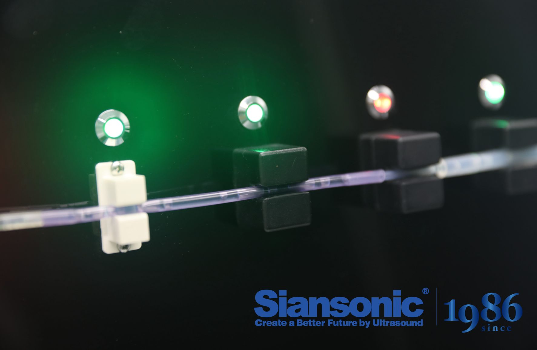
The calibration process for each air bubble detector begins with a set of NIST-traceable phantoms that simulate the acoustic properties of blood and tissue. These phantoms contain precisely engineered microbubbles of known diameters, ranging from 20 to 500 microns, embedded in a gel matrix. By passing the detector over each phantom at a controlled flow rate, the system's sensitivity threshold is mapped against reference standards, allowing for correction of any drift in transducer response or signal processing.
Unlike generic factory calibrations, this method ties every detector to a documented chain of measurements back to NIST primary standards. Technicians record the minimum detectable bubble size, the false-positive rate at baseline, and the linearity of the amplitude output. These data are stored in the detector's onboard memory, so that future recalibrations can be compared against the original signature. Any deviation beyond ±5% triggers an automatic flag, prompting a full diagnostic cycle before the device is returned to service.
Field experience shows that detectors calibrated against NIST-traceable phantoms maintain consistent performance across temperature fluctuations and tubing variations. In one pediatric cardiac unit, switching to this protocol reduced false alarms caused by microclots from 12 per shift to fewer than 2, without missing a single clinically relevant air embolus. The phantoms themselves are revalidated annually, ensuring that the traceability chain remains unbroken and that each detector's calibration reflects the latest metrological consensus.
Choosing Polymers That Survive Aggressive Fluids Without Fogging
Finding a polymer that holds up in aggressive chemical environments while staying clear of fog is a tougher ask than most design teams expect. Standard anti-fog treatments rely on hydrophilic surfaces that spread condensation into a thin, transparent film, but those same coatings often wash away or degrade when exposed to solvents, acids, or caustic cleaners. The real trick is selecting a base resin whose inherent surface energy and chemical resistance already lean in the right direction—materials like cyclic olefin copolymers, polysulfone, or certain fluoropolymers can shrug off many aggressive fluids, yet their natural tendency to bead water means fogging remains a battle unless you modify the surface without sacrificing durability.
Rather than bolting on a fragile anti-fog layer, some engineers look for polymers that can be plasma-treated or lightly functionalized to reduce the water contact angle permanently. Polycarbonate, for example, offers decent impact strength and some chemical resistance, but its fogging behavior is poor out of the box; a gentle oxygen plasma etch can create hydroxyl groups that improve wetting without compromising the bulk material's resistance to many industrial fluids. The catch is that aggressive fluids like ketones or chlorinated solvents will still attack the polymer backbone, so you need to cross-reference the actual exposure list—not just a generic "chemical resistance" datasheet—against realistic contact times and temperatures. A polymer that survives a splash test might craze after sustained immersion.
In practice, the selection process often comes down to trade-offs between optical clarity, mechanical toughness, and tolerance for specific fluid families. Polyetherimide and polyetheretherketone can withstand harsh cleaners and high heat, but their inherent haze or amber tint may rule them out for vision-critical applications. That pushes many teams toward multi-layer constructions: a robust, chemically resistant outer shell paired with a thin, permanently hydrophilic inner surface achieved through co-extrusion or in-mold coating. Testing prototypes under thermal cycling and repeated fluid exposure is non-negotiable, because fog-free performance in a fresh sample rarely predicts long-term behavior once micro-cracks or surface roughening set in.
Automated Vision Checks for Bubble Size Accuracy
In many production lines, tiny bubbles trapped in a fluid or film can affect product quality, but manual inspection can't keep up with throughput. Automated vision checks fill this gap by capturing high-resolution images at line speed and measuring each bubble's diameter, area, and roundness against predefined tolerances. Because the system learns from a reference set of acceptable and rejected samples, it flags only meaningful deviations instead of every minor variation.
Lighting and camera alignment matter more than most people expect. A ring light or backlight creates sharp contrast at the bubble edges, so edge-detection algorithms can trace contours reliably. Calibration with a known-size target keeps measurements accurate across different batches, and periodic self-checks warn operators if focus drifts or debris builds up on the lens. Rather than relying on a single pass/fail threshold, many setups now store size distributions over time, which lets process engineers spot gradual shifts before they cause a full reject.
This approach also reduces operator fatigue and disagreement between inspectors. One person might classify a borderline bubble as acceptable in the morning and reject a similar one later in the shift. Automated vision checks apply the same criteria every time, and the saved images give a clear audit trail. When a new bubble size issue appears, technicians can pull historical frames, compare patterns, and adjust upstream parameters such as mixing speed or degassing time with confidence.
Designing Flow Cells That Fit Non-Standard Tubing Sets
Flow cells are often designed around standard tubing dimensions, but real-world lab setups rarely cooperate. When you have a non-standard tubing set from a legacy instrument or a custom manifold, the default flow cell geometry can create dead volumes, leaks, or uneven flow splitting. The first step is to map the actual inner diameter, wall thickness, and connector style of every tubing segment that will interface with the cell. Rather than forcing the tubing to match the cell, design the cell's inlet and outlet ports as modular inserts — small, replaceable compression fittings or tapered bushings that can adapt to a range of outer diameters without sacrificing a smooth transition into the optical chamber.
Once the physical interface is sorted, focus on the internal channel shape. Non-standard tubing often has different stiffness and bend radii, which means the flow cell must absorb mechanical stress instead of transmitting it to the detector window or gasket. A short, flexible relief zone just inside each port — something like a serpentine microchannel or a bellows-like cavity — lets the cell tolerate slight misalignments and vibration from the tubing run. At the same time, keep the cross-sectional area of the relief zone close to that of the tubing's inner lumen to avoid sudden velocity changes that can cause air bubble nucleation or sample carryover.
Finally, test the cell under actual flow conditions rather than on a bench with perfectly straight tubing. Use the real non-standard set, route it through the same bends and clips as in the instrument, and look for pressure drop anomalies or particulate settlement at the interface. If the cell is intended for optical interrogation, check that the non-standard tube's refractive index and wall thickness don't create stray light reflections at the entry window. Small chamfers or a slight angle on the port bore can often eliminate these artifacts without changing the tubing set at all.
Pulsatile Flow Testing That Mimics Real Infusion Pumps
Recreating the irregular, pulsing output of an actual infusion pump is harder than it sounds. Most test rigs deliver a smooth, steady stream, but patients rarely receive fluid that way. Small peristaltic rollers, syringe plunger stutter, and tubing compliance all introduce rhythmic pressure spikes and brief flow drop-offs. Our bench setup uses a custom cam-driven mechanism paired with measured tubing elasticity to reproduce those micro-fluctuations, so the downstream sensor or catheter sees the same messy waveform it would encounter in a hospital room.
What makes this approach different is that we don’t just average the pulsation out. We capture the peak-to-trough amplitude, the frequency of the pulses, and the dampening effect of long infusion lines. That lets us verify whether a flow meter under test can track a 0.2 mL/h basal rate with superimposed 0.05 mL boluses, or if it gets confused by the backflow spike when the pump cycle resets. The data we collect often reveals failures that steady-flow testing completely misses.
FAQ
The sensing chamber is machined to a tolerance of ±0.005 mm on critical diameters, because even a slight ovality can scatter the ultrasonic or optical signal and create false bubble counts. Laser micrometers verify these dimensions on every batch before sensor assembly.
We age-test the piezoelectric or optical emitters for 200 hours under elevated temperature and then re-characterize their output curves. Only components whose threshold shift stays under 2% are accepted, and each sensor is digitally compensated for the remaining drift during final calibration.
The fluid-contact parts are assembled inside an ISO Class 7 cleanroom with positive air pressure. Operators wear full gowns, and all wetted surfaces are plasma-cleaned before bonding to remove trace oils that could later leach into saline or pharmaceutical lines.
The slurry-line version uses a sapphire optical window and chemically resistant PEEK housing, while the dialysis version relies on medical-grade polycarbonate and a softer ultrasonic coupling gel. Both share the same sensing core, but the wetted material set and sealing method are completely different.
We inject a known sequence of micro-bubbles from a calibrated glass capillary while the fluid flows at three different rates. The detector must flag every injected bubble with no more than a 30-millisecond latency and produce zero false positives over a 10-minute clean-flow baseline.
No two ultrasonic crystals or photodiodes have identical temperature coefficients, so a fixed curve would drift outside acceptable limits in some units. Individual calibration maps the sensor's response at five temperatures and stores the coefficients on an onboard EEPROM.
The unit is first run on a reference bench to reproduce the reported fault. Then we de-pot the electronics and inspect the solder joints under X-ray, because micro-cracks in the transducer bond are a common root cause. The findings are logged against the original production lot to trigger a wider review if needed.
Conclusion
Inside an air bubble detector factory, the path to reliable fluid monitoring is built on controlled conditions rather than last-minute fixes. Optical sensors are assembled under laminar flow, where filtered air keeps every lens and emitter free from microscopic dust that could scatter light. Calibration then ties each detector to NIST-traceable phantoms, so a 50-microliter bubble triggers the same response in Unit 4 as in Unit 400. Polymer choices matter just as much: the flow cell material must shrug off aggressive cleaners, lipids, and solvents without fogging or micro-cracking, because any haze on the optical window changes the baseline signal. Instead of accepting off-the-shelf plastics, the factory tests candidate resins under accelerated aging to see how they hold up over months of continuous contact.
Downstream from assembly, automated vision systems inspect bubble size accuracy by pumping known air slugs through every flow cell and measuring their dimensions against preset tolerances. This catches drift in sensor gain or lens alignment that manual checks would never see. For real-world fit, flow cells are designed to accommodate non-standard tubing sets, including silicone, PVC, and multi-layer coextrusions with uneven wall thicknesses. The geometries are validated under pulsatile flow that mimics actual infusion pumps, complete with systolic-like spikes and pump-induced pressure waves. Only when a detector hears the bubble signal above that noisy background does it leave the line. That sequence—laminar assembly, traceable calibration, tough materials, and dynamic validation—turns a small optical sensor into a dependable part of an infusion safety loop.
Contact Us
Contact Person: Ivy Zhang
Email: [email protected]
Tel/WhatsApp: +86 1081502288
Website: https://www.siansonic.com/