

China Spray Column: A Comprehensive Guide to Industrial Applications and Design
2026-11-16
In many gas-cleaning and absorption processes, the spray column does the heavy lifting—yet it rarely gets the attention it deserves. This guide breaks down how these columns are engineered for real industrial duty, from nozzle placement to pressure drop, and why design choices ripple through performance. Along the way, we look at practical examples from Sinou, a Chinese manufacturer whose spray column solutions are built for demanding environments.
How Spray Columns Handle High-Dust and High-Temperature Gas Streams
Spray columns thrive in environments that would quickly clog packed beds or overwhelm cyclones. By relying on a simple open-chamber design with no internal packing, they avoid the accumulation of fine particulates on structured surfaces. The scrubbing liquid, typically water or a tailored reagent slurry, is atomized into fine droplets through high-pressure nozzles. As dust-laden gas rises through the chamber, these droplets collide with particles, capturing them through impaction and interception. Because the liquid is continuously renewed and drained downward, there is no static media for dust to build upon, making the column inherently resistant to fouling even with heavy dust loads exceeding several grams per cubic meter.
Temperature management is another core strength. The large volume of recirculated liquid acts as a direct-contact heat sink, rapidly cooling hot gas streams without the need for upstream quench towers. A spray column can drop inlet gas temperatures from over 800°C to near the adiabatic saturation point in a matter of seconds, depending on liquid flow and droplet size distribution. This prevents thermal damage to downstream equipment and allows the use of less expensive materials for ducting and fans. Evaporation of a portion of the spray also increases gas humidity, which can improve subsequent particulate collection or acid-gas removal in integrated systems.
Real-world installations often combine these two capabilities. For instance, in mineral processing or waste incineration, a single spray column may serve as both a primary dust scrubber and a gas cooler. Operators adjust nozzle pressure, liquid-to-gas ratio, and droplet residence time to balance removal efficiency with pressure drop. The absence of internal obstructions keeps energy consumption modest, while the rugged design tolerates abrasive dusts and corrosive thermal loads that would degrade traditional filtration or packed-bed technologies within weeks.
Nozzle Layout and Internal Flow Patterns That Drive Absorption Efficiency
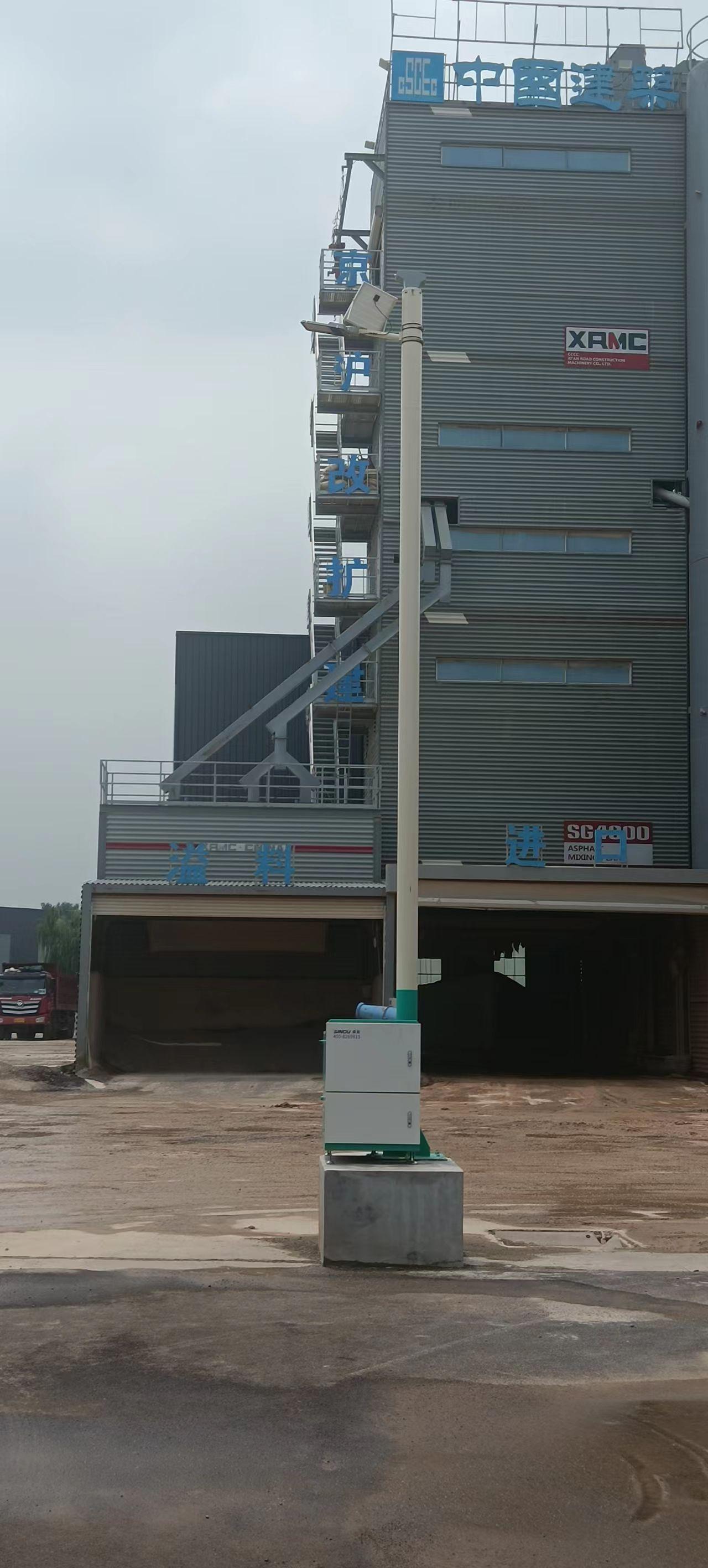
Nozzle placement rarely gets the credit it deserves. When nozzles are arranged in staggered rings rather than a simple grid, the liquid curtains overlap in a way that forces gas through continuously shifting film thicknesses. That variation keeps local absorption rates from plateauing. A ring-stagger pattern also prevents the dry channeling that appears when straight-line arrays leave gaps between spray cones.
Inside the tower, the real story is recirculation. As droplets decelerate, they drag gas along and create toroidal vortices just beneath each spray level. These vortices pull partially stripped gas back into the liquid-rich zone instead of letting it slip upward along the wall. The result is a longer effective contact time without any increase in residence volume.
What matters most is the interaction between nozzle angle and internal downcomer position. A wide cone angled slightly inward drives liquid toward the column center, which strengthens the central updraft and evens out the radial velocity profile. That balance reduces wall wetting and keeps the absorption front from tilting, which is exactly what you need when turndown conditions would otherwise starve the outer packing ring.
Choosing Structural Materials for Acidic and Chloride-Rich Service
Acidic, chloride-laden environments punish structural alloys in ways that generic corrosion tables rarely capture. The combination of low pH and aggressive halide ions strips away passive oxide films faster than either factor alone, turning pitting and crevice attack into the dominant failure modes. Standard austenitic grades like 304 and 316, often specified for mild chemical service, become poor choices once chloride levels climb above a few hundred ppm at elevated temperatures—localized breakdown can occur within weeks, not years. Simply adding more chromium or molybdenum helps, but the real selection hinges on the specific acid chemistry, temperature cycling, and whether deposits or tight joints create stagnant zones.
Among the realistic candidates, nickel-based alloys such as C-276 and 625 offer broad resistance to hydrochloric and sulfuric acid mixes with chlorides, but their high alloy content makes fabrication and cost difficult to justify for large vessels. Titanium grades, particularly Gr.2, excel in oxidizing acidic brines—think hot seawater with chlorine injection—yet fail rapidly in reducing acids like hot dilute HCl. Super duplex stainless steels (e.g., 2507) strike a middle ground, with good pitting resistance and higher strength, but their performance degrades sharply if the acid contains fluorides or if crevice geometry cannot be avoided. No single alloy wins across all acidic chloride scenarios; the choice depends on whether the acid is oxidizing or reducing, the chloride concentration, and the presence of abrasive solids that could remove protective films.
Practical selection therefore demands more than consulting a corrosion chart. Run electrochemical tests—critical pitting temperature, cyclic potentiodynamic polarization—using actual process fluids, because trace contaminants like ferric ions or oxygen can shift the corrosion mechanism. Weld qualification is equally critical: heat-affected zones often become initiation sites, so filler metals must match or exceed the base alloy’s pitting resistance, and post-weld pickling may be unavoidable. Finally, weigh the total lifecycle cost. A cheaper duplex steel might survive for five years in a mild acidic brine, while a hastelloy vessel lasts twenty—but if the duplex replacement cost and downtime are lower, the “inferior” material can still be the better engineering decision.
Balancing Pressure Drop, Pumping Energy, and Capture Rates
Engineers working on gas separation quickly learn that capture rate, pressure drop, and pumping energy are locked in a three-way trade-off. Achieving high capture rates usually means increasing gas-liquid contact area and residence time, which in turn raises frictional resistance through the absorber or contactor. That added pressure drop translates almost directly into higher blower or fan power, so a capture system optimized only for removal efficiency can become surprisingly expensive to operate.
The practical levers are finite. Swapping random packing for structured packing can cut pressure drop per meter of bed while preserving mass transfer, but it does not eliminate the underlying tension. If solvent flow is reduced to save pump energy, absorption rates may fall unless the solvent velocity or temperature is adjusted elsewhere, which brings its own penalty. Some operators lower gas velocity to keep pressure drop in check, only to find that the required column diameter grows and capital cost climbs.
In many retrofit and new-build designs, the better question is not how to minimize pressure drop or maximize capture rate in isolation, but how to find the point where the next increment of capture stops being worth the added energy. Plotting pumping energy per tonne of CO2 captured against capture rate often reveals a shallow optimum between roughly 85% and 90%, beyond which pressure drop rises steeply. That is why balance—rather than an extreme target—tends to dominate final design choices.
Real-World Installations Across Chemical, Power, and Metallurgical Sectors
Across chemical plants, power stations, and metallurgical facilities, real-world installations reveal a pattern of adaptation that no single specification sheet captures. A chlor-alkali unit in Louisiana, for instance, pairs corrosion-resistant alloys with modular sensor arrays to survive brine mist and fluctuating chlorine concentrations. The layout isn't elegant on paper—cable trays zigzag around existing ductwork, junction boxes sit at odd heights—but every compromise answers a specific failure mode logged during the first year of operation.
In thermal power generation, the story shifts to high-temperature vibration and fly ash. One coal-fired station in Poland replaced a traditional thermowell with a stepped-bore design after repeated resonance fractures. The fix wasn't about using a more exotic material; it was about changing the geometry so that the natural frequency moved away from the turbine's harmonic spikes. Similar logic drives metallurgical installations: a copper smelter in northern Chile runs oxygen lances with water-cooled jackets that are monitored by fiber-optic temperature sensing, not because it's cutting-edge, but because thermocouples kept failing at the slag line.
What ties these sites together is how maintenance records shape future choices. A steel mill might stick with a seemingly outdated pneumatic control system because the electrical noise from arc furnaces keeps frying digital transmitters. A petrochemical complex may duplicate pressure relief paths after a near-miss during a power dip. These aren't design flaws or triumphs—they're the accumulated scar tissue of industrial reality, where a 'standard' installation is just a starting point that gets rewritten by the first unplanned shutdown.
Troubleshooting Wet Wall, Scaling, and Uneven Gas Distribution
Wet wall symptoms often show up as persistent moisture filming on vessel walls, droplet carryover into downstream ductwork, or a drop in absorption efficiency. Start by checking the liquid distribution system—clogged spray nozzles or a tilted distributor tray can send too much liquid toward the shell while leaving the core dry. Also verify the gas velocity. When it runs above design limits, the shear force drags liquid upward and outward, creating that wet wall effect even if the internals look clean.
Scaling usually follows a pattern: hard water chemistry, local hot spots, or stagnant zones where dissolved solids drop out. If you see crusty deposits near the wet-dry boundary, that is a classic sign of evaporation-driven scale rather than bulk precipitation. Rather than reaching for aggressive chemicals immediately, try mapping the deposit thickness and color first. White or off-white scale often points to calcium carbonate; darker, rougher buildup can indicate sulfate salts or corrosion byproducts. Adjusting blowdown rates and switching to a more forgiving pH band will often slow the scaling enough to extend run times between cleanings.
Uneven gas distribution is rarely solved by a single damper tweak. It is usually a geometry problem: an undersized inlet plenum, a sudden expansion downstream of the fan, or partially plugged holes in a distributor plate. Use a pitot traverse across the vessel cross-section to find the high- and low-flow regions before changing anything. Then consider adding turning vanes, redistributing the open area on the plate, or installing a perforated baffle to break up jets. In many cases, a small change in duct approach angle gives a bigger improvement than increasing fan speed.
FAQ
Focus on the liquid distributor and nozzle arrangement rather than just shell thickness. A well-built unit will show even spray coverage across the full cross-section, with no dry spots near the walls. Ask for wet-test videos or pressure-drop curves under your expected gas load. Also check if the manufacturer has experience with your specific chemistry, because materials like PP or FRP need different welding standards than stainless steel.
Spray columns handle dust-laden gas far better because there is no packing to plug. The open internal space lets solids pass through while the scrubbing liquid captures acid gases. The trade-off is lower mass-transfer efficiency per unit height, so you often need a taller vessel or multiple spray stages. For high-dust conditions, this is usually cheaper than constantly cleaning or replacing packed beds.
Flue gas desulfurization in power plants, wet scrubbers for chemical plants, and odor control in food processing all see strong demand. Chinese suppliers have built a lot of experience in these sectors, especially for large-diameter columns that would be cost-prohibitive elsewhere. The key is to specify your gas composition and particulate load clearly so the column is not just a generic design.
Use hollow cone nozzles that produce smaller droplets at lower pressure, and consider adding a mist eliminator near the outlet to reduce carryover. A packed mist eliminator can also act as a second contact zone, squeezing more transfer from the same liquid. Inlet gas distribution matters just as much: a tangential entry or a perforated plate will prevent short-circuiting and keep the spray pattern stable.
Routine inspection of nozzle wear is the most important task. Even a 10% increase in nozzle orifice size shifts droplet size and reduces scrubbing efficiency, while also increasing liquid consumption. Use a quick-connect nozzle design for easy replacement, and keep a log of spray pressure at a fixed flow rate. For slurry service, flush the bottom cone with clean water during shutdowns to prevent solids from hardening and blocking the drain.
Look at the design documentation. A custom unit will include a gas-liquid contact profile, droplet trajectory estimates, and a materials recommendation based on your exact temperature and pH. A standard unit usually has a fixed diameter, a generic nozzle array, and little flexibility in inlet orientation. Custom builders will also ask about turndown ratio and emissions limits, because those drive the number of spray stages and the type of mist eliminator.
Freight is significant because large columns ship as multiple sections and need special handling. Internal components like nozzles and mist eliminators may be packed separately. Don't overlook the cost of third-party inspection during fabrication, which can catch welding defects before shipping. Also, factor in longer lead times for custom alloy internals, and confirm whether the supplier uses export-grade crating to avoid damage in transit.
Conclusion
China’s spray column technology has proven remarkably adaptable in handling gas streams laden with heavy dust and sustained high temperatures, a challenge common in smelting and incineration. The key lies in arranging multiple spray levels so the liquid curtain intercepts particulates before they can cake on internals, while internal baffles and carefully selected nozzle angles create a swirling, downward-directed flow that extends gas-liquid contact time. Rather than relying on a single design parameter, engineers balance pressure drop against pumping energy; too aggressive a spray boosts capture rates but wastes power and can flood the mist eliminator. Field experience shows that an optimized layout—often with counter-current stages and a coarse-to-fine droplet sequence—keeps absorption efficiency high without driving fan loads beyond practical limits.
Material selection is equally decisive, especially in acid plants and chloride-rich waste incineration where carbon steel fails quickly. Many Chinese fabricators now specify fiberglass-reinforced plastic, duplex stainless, or resin-lined carbon steel for the shell and use silicon carbide or PTFE nozzles to resist erosion and chemical attack. Installations across chemical, power, and metallurgical sectors reveal consistent lessons: wet wall formation is usually traced to poor gas distribution or nozzle plugging, while scaling responds to adjusted liquor chemistry and periodic high-pressure washing. Uneven gas distribution, a frequent cause of short-circuiting, is corrected by adding perforated distribution plates or reshaping the inlet duct. In practice, operators monitor differential pressure and outlet opacity together, treating the column not as a fixed device but as a system that demands periodic tuning of spray patterns, liquid rates, and internal geometry to match shifting feedstock and emission limits.
Contact Us
Contact Person: HaiYan
Email: [email protected]
Tel/WhatsApp: +86 18957325588
Website: https://www.senyoubeton.com/