

Custom Expanded PTFE Gasket Guide for Engineers and Maintenance Teams
2026-11-17
If your sealing strategy still treats every flanged joint the same, you’re already leaving performance on the table. Custom expanded PTFE gaskets are quietly replacing conventional options in chemical plants, food processing lines, and high-cycle maintenance environments, but most guides stop at generic specs. This one doesn’t. Written for engineers and maintenance teams who deal with irregular surfaces, aggressive media, and tight bolting windows, it walks through material selection, dimensional tailoring, and failure patterns you won’t find in a standard datasheet. Along the way, we’ll reference how TAIFNO approaches custom profiles and tolerances, so you can evaluate what actually matters before the next shutdown. No fluff, no recycled vendor language—just the details that decide whether a gasket seats perfectly or becomes the weak link in your flange.
Gasket Creep and Load Retention in Cyclic Service
In cyclic service, gaskets rarely fail from a single overload event. More often, the joint loses clamping force over time because the gasket material creeps away from the contact faces. This slow thickness reduction is not always visible during a shutdown inspection, yet it directly lowers the residual stress on the sealing element. Once the available seating stress drops below the minimum required for the operating pressure, a leak path begins to open, usually at the interface where the gasket meets the flange.
Load retention is the other side of the same problem. Even when a gasket shows acceptable short-term creep, repeated temperature swings and pressure cycles can accelerate relaxation. Each thermal cycle expands and contracts the joint components at different rates, and the gasket absorbs much of that differential movement. Over time, the fastener preload decays in a stepwise fashion rather than smoothly. Bolts that were correctly torqued at ambient temperature may carry only a fraction of their original tension after several hundred cycles.
Material choice and surface finish matter here more than higher bolt torque alone. Dense graphite and filled PTFE tend to retain load better under thermal cycling, while some fiber-based sheets creep excessively once the binder softens. A practical approach is to measure residual bolt load during service or validate creep relaxation data against the actual flange stiffness, then set re-torque intervals where access permits. Without that, specifying a higher initial stress often just shortens the time to gasket damage rather than solving the underlying loss of load.
Surface Finish Requirements Before Custom PTFE Installation
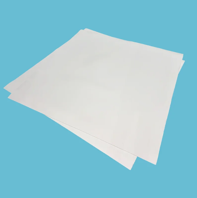
Most PTFE lining failures that get blamed on the material actually start with the substrate. Before any custom PTFE sheet or film goes down, the metal surface needs to be dry, oil-free, and free of rust, mill scale, and old coating residue. A solvent wipe alone is not enough if the surface still feels slick or shows a dull haze. Use a two-step clean: first remove heavy contamination with a degreaser, then wipe down with a lint-free cloth and a fast-flashing solvent that leaves no film behind.
Roughness and profile matter more than many installers expect. A mirror-smooth surface gives the adhesive or bond layer very little to grip, while a surface with sharp peaks can create thin spots in the PTFE under pressure. For most custom PTFE installations, a uniform profile in the 2.5 to 4 micron Ra range works well, with weld seams ground flush and any pinholes or undercut edges repaired before cleaning. If you can catch a fingernail on a seam or edge, it will likely read through the PTFE later.
Timing is the last part of the equation. Once the surface is prepped, install the PTFE before condensation, flash rust, or shop dust settles back onto the metal. If the substrate temperature is below the dew point, wait. Bare hands should stay off the prepared area because skin oils create local adhesion problems that are easy to miss during a visual check.
Bolt Torque Sequencing for Uneven Flange Faces
Uneven flange faces rarely respond well to a fixed torque pattern copied from a manual. Start by bringing the mating surfaces into light contact with all bolts finger-tight, then measure the gap around the circumference with feeler gauges. The widest gap shows where the joint needs to be drawn down first, not the opposite side.
Begin the first torque pass at that widest point and work outward in a staggered or star sequence, alternating across the diameter rather than moving around the bolt circle. Keep the initial pass low, roughly thirty percent of final torque, so the flange can settle without pinching the high spots. On the next passes, increase in thirds and watch for changes in the remaining gap. If one side closes much faster than the other, pause and ease off the nearest bolts slightly before continuing.
When the face is visibly out of flat beyond what sequencing can correct, consider using controlled-thickness shims at the low spots before final tightening. Final torque should be reached in at least three stages, and a repeat check after the last bolt often reveals relaxation that needs a small nudge. This approach helps prevent gasket crushing and uneven bolt load more effectively than simply following a standard crisscross pattern.
Reading Chemical Compatibility Charts for Blended Process Streams
Blended process streams tend to undercut the neat, single-chemical ratings printed in most compatibility charts. A chart may show that a fluoroelastomer handles both toluene and methanol at a given temperature, yet a 50/50 mix of the two can swell or craze the same material because the combined solvent activity shifts outside the range covered by either pure component. Reading these charts for mixtures requires treating each listed chemical as a starting point rather than a guarantee, and paying attention to the concentration, operating temperature, and the presence of trace species that often carry more aggressive behavior than the bulk stream.
A practical approach is to identify the harshest constituents first, not simply the largest ones by volume. Look up the rating for each component against the candidate polymer or metal, note the lowest compatibility score, and then assess whether the mixture could create a more aggressive condition—such as hydrolyzing into an acid, generating free chlorine, or shifting pH beyond the material’s stable window. Chart footnotes and temperature correction curves matter just as much as the letter or color rating, because a material listed as “good” at room temperature may fail rapidly once a blended stream carries a small amount of an amine or organic acid that depresses the effective service limit.
Where the blended composition falls outside documented combinations, a soak test under actual process conditions is often more useful than extrapolating from generic charts. Elastomer and plastic suppliers sometimes maintain internal data on common solvent pairs, refrigerant blends, or acid-organic mixtures, and those records can fill gaps that public charts leave open. Pay attention to the direction of flow and the possibility of phase separation as well, since a stagnant layer rich in one component can attack a gasket or sensor even when the bulk mixture looks mild on paper.
Early Warning Signs of Expanded PTFE Gasket Distress
Expanded PTFE gaskets rarely fail without sending a few clear signals first. The earliest visual cue is often a slow, creeping squeeze-out along the flange edge—material that looks like thin, waxy webbing beginning to escape the seating area. This is easy to dismiss during routine checks, but it usually means the gasket is losing its compressive grip, especially on glass-lined or plastic flanges where bolt loads are already kept low. You may also notice a faint glossy sheen on the outer rim, suggesting the material has started to cold-flow under sustained pressure rather than holding its original shape.
Another overlooked sign is a change in surface texture. A healthy expanded PTFE gasket feels dense but slightly velvety; one under distress often becomes stiff, cracked, or takes on a faint chalky residue at the edges. In services with thermal cycling, hairline fissures may appear around the inner bore, where the material expands and contracts at a different rate than the flange. If you catch these before a full-blown leak, the fix is usually straightforward—lowering torque on the problem bolts or switching to a thicker, more conformable grade—rather than waiting for process fluid to etch a visible path across the gasket face.
Finally, pay attention to how the gasket sounds and behaves during a shutdown. A distressed expanded PTFE gasket often separates from the flange with a brittle snap instead of peeling away cleanly, and the seating surface may show permanent indentation marks that do not recover after the load is removed. Those imprints, especially if they are uneven from bolt to bolt, point to localized over-compression that will prevent a proper seal on the next assembly. Replacing the gasket at this stage costs far less than chasing fugitive emissions or dealing with a flange face that has been chemically attacked through a compromised seal.
Rework and Replacement Intervals Without Unplanned Downtime
Balancing maintenance schedules against production demands often forces a choice between risking unexpected failures and sacrificing output for precautionary stops. Rework and replacement intervals that truly avoid unplanned downtime depend on reading the actual condition of critical components, not just counting hours or cycles. When wear patterns, material fatigue, and environmental stress are monitored continuously, teams can plan interventions around natural production pauses, shift changes, or scheduled batch ends without losing runtime.
The practical value shows up in how work orders are staged. Instead of replacing a bearing because a generic calendar window has closed, maintenance crews pull parts and assign labor only when measured drift suggests a realistic remaining life of days or weeks. This narrows the gap between doing too much and doing too little, while keeping the line moving. It also reduces the cascade effect of opening equipment for an unnecessary swap and introducing new failure risks during reassembly.
Over time, the data collected from each rework tells its own story. Intervals can be stretched or shortened based on what the machinery actually experiences, not on a static manual. That feedback loop makes future replacements more predictable and helps procurement avoid both stockouts and overstock. The result is a maintenance rhythm that feels less like a cost center reacting to emergencies and more like a deliberate, low-drama part of operations.
FAQ
The material is stretched into a highly fibrillated structure, so it conforms to scratched or slightly warped flanges with much lower bolt load. That same structure also creeps more and has lower tensile strength than rigid or filled sheet, so gasket dimensions, thickness, and flange support need separate review instead of being inherited from an old cut-gasket spec.
Work from field measurements, not just the piping isometric or old vendor print. Measure the raised face, bolt circle, and actual sealing width, then specify the gasket ID slightly larger than the bore so it cannot intrude into the flow stream. Keep the OD within the raised face or controlled compression area, and call out thickness only after checking flange flatness and available bolt load.
Expanded PTFE relaxes as the fibrils settle, and the first heat cycle accelerates that relaxation. A hot retorque can help if the flange, bolts, and gasket were designed for it, but it also introduces a safety and consistency problem on large equipment. The better approach is to choose the correct thickness and stress level up front, use disc springs or controlled bolting where needed, and verify residual load before deciding to retorque.
Custom shapes earn their cost when you are sealing non-standard flanges, rectangular manways, glass-lined equipment, heat exchanger covers, or damaged sealing faces that need a softer conformable material. If the joint is circular, common size, moderate temperature, and easy to reach, a stock gasket usually works. If the flange is odd, fragile, or hard to seal without high bolt load, a custom ePTFE part becomes a practical fix.
Remove old gasket debris, oil, and scale. Light radial scratches can usually be tolerated because the material will flow into them, but deep radial scoring, pitting, and uneven flange surfaces need mechanical repair. Check flatness with a straight edge and feeler gauge, and confirm the flange faces are parallel before bringing bolts up. The gasket compensates for minor irregularity, not for misalignment.
Reuse is rarely worth it. Once compressed, the material has already lost much of its recovery, and a used gasket may not reseal the same set of irregularities when the flange is disturbed. In a clean, low-pressure, non-critical utility joint you might get away with it in an emergency, but for process services, fragile flanges, or thermal cycling, installing a new gasket is cheaper than a second leak repair.
Keep them flat, clean, and out of direct sunlight or ozone sources. Avoid hanging them on nails, stacking heavy parts on top, or folding thin sheets. Store away from solvents and sharp edges, and keep them in sealed bags if the area is dusty or humid. The material has a long shelf life when protected, but mechanical damage from rough handling causes more early failures than age itself.
Some thickness reduction is normal because ePTFE is designed to densify under load. If compression is not controlled, the gasket can extrude or split, especially on thin, wide gaskets or raised face flanges with limited containment. Use a torque pattern and staged tightening, monitor thickness change where possible, and stop if the gasket edge shows heavy extrusion or the flange gap becomes visibly uneven.
Conclusion
Most custom expanded PTFE gasket problems appear after the first handful of thermal cycles rather than during initial hydrotest. In cyclic service, creep rarely announces itself as a sudden blowout; it shows up as a slow drop in bolt load once the joint sees repeated heating and cooling. Rechecking torque after the first 10 to 20 cycles, with the flange near operating temperature where permitted, does more to hold a seal than simply pulling the bolts harder at assembly. Surface preparation matters just as much. A clean, dry finish in the 125 to 250 microinch Ra range usually gives expanded PTFE enough grip, but scratches, pitting, or old gasket residue can create a path for pressure to escape even with a new gasket installed. On flanges with uneven gaps, a fixed star pattern is not enough; start from the widest side and bring the joint down in at least three passes, measuring the gap as you go. For blended streams, single-component chemical charts can mislead because mixtures can shift pH, accelerate filler attack, or change permeation. Check the harshest continuous component at the actual upper temperature instead of relying on average process conditions.
Distress usually gives a warning before a leak. Thinning at the outer edge, cold flow beyond the flange rim, local discoloration, or visible shrinkage after thermal swings all indicate that the gasket is being asked to absorb more movement than the joint can handle. These are maintenance signals, not immediate reasons to shut down. Teams that log bolt load and gasket thickness after each minor inspection can plan replacement during scheduled batch changes or short venting windows. Setting a rework interval from that history is more reliable than following a generic calendar date, because line temperature, pressure spikes, and mix composition differ from one system to the next. Pulling a gasket early based on visible distress costs far less than an unplanned outage later. Over time, the inspection notes become a practical guide for each flange, showing whether the current gasket can survive another cycle or should be swapped before the next startup. This turns replacement from an emergency repair into a controlled, budgeted task.
Contact Us
Contact Person: Tommy Xiao
Email: [email protected]
Tel/WhatsApp: 8615651509888
Website: https://www.ptfe-factory.com