
Sanitary Ware Vertical Lift Plating Equipment Guide for Modern Manufacturers
2026-11-02
Getting a mirror-bright finish on every curved faucet and concealed shower part is a daily battle for sanitary ware manufacturers. Vertical lift plating equipment is quietly reshaping how high-mix, high-quality lines are built—offering faster cycle times, better drainage, and fewer rejects. In this guide, we break down what modern manufacturers need to know, drawing on field-proven insights from Junda.
Vertical Lift Plating Equipment That Keeps Up With Mixed Sanitary Ware Runs
Mixed sanitary ware runs rarely mean uniform loads. Basins, pedestals, and cisterns each shift the balance point and current demand, so the vertical lift system reads the rack profile and adjusts stroke length, entry angle, and dwell timing on the fly. That keeps thinner brass or zinc parts from burning while heavier ceramic-backed fittings still get full coverage.
Rapid changeover matters more than top speed in a line that switches part families several times a shift. The lift uses stored recipes tied to fixture barcodes or RFID tags, so operators don't retune agitation or rectifier curves by hand. A switch from a deep bowl to a shallow tray takes under a minute, and the first cycle after changeover runs with the same repeatability as the hundredth.
Mechanical wear is where many vertical lifts fall short. This design isolates the carriage rails from chemical mist and uses sealed linear bearings with automatic lubrication, so lost motion stays below a millimeter even after months of uneven loads. The result is a stable anode-to-cathode gap that holds thickness variation within tight limits across mixed production.
Jig and Rack Setups for Even Chrome Coverage Inside Deep Bowls
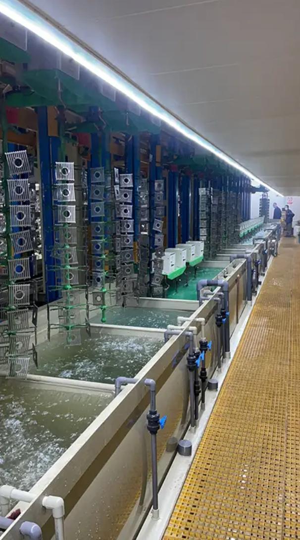
Getting chrome to reach the bottom of a deep bowl is less about cranking up the current and more about how the part sits on the rack. A standard vertical hang leaves the interior starved of current, especially below the rim where the solution flow goes stagnant. One practical fix is to angle the bowl 15–30 degrees with the opening facing the anode and slightly downward, so hydrogen bubbles can escape instead of pooling against the inside wall. Combine that with a rack contact placed on the outside bottom edge, and you give the recessed area a better shot at seeing the anode field.
For bowls deeper than about two diameters, a central auxiliary anode makes a real difference. A thin platinized titanium wire or small conforming anode running down the middle of the bowl pushes current directly into the bottom and sides. It should be insulated where it passes through the upper section, so you don’t overplate the rim before the lower areas build thickness. You can also attach a non-conductive deflector or current robber around the rim to redirect current toward the interior, which helps even out the deposit without overplating sharp edges.
Finally, don’t let the rack geometry trap solution. Deep bowls need positive solution movement inside, so position air agitation lines or eductors to push fresh electrolyte into the cavity, not just around the outside. Multiple small drain holes at the lowest point of the bowl—if the design allows—will stop the part from dragging out contaminated solution and keep the interior flow pattern stable. This combination of tilt, central anode, and directed circulation typically gives a much more uniform chrome layer inside than simply extending the plating time.
Rectifier and Anode Placement Strategies for High-Gloss Nickel Layers
Achieving a mirror-like finish in nickel electroplating depends heavily on how current is delivered and how anodes are positioned. Many plating shops overlook the fact that rectifier settings and anode geometry work together to control local current density across the part. When the current distribution is uneven, high-gloss nickel will show haze, burning at edges, or dull patches in recessed areas—even if the bath chemistry is perfectly balanced.
A practical approach starts with matching the rectifier output to the total surface area, but that alone is not enough. Anodes placed too close to sharp corners create excessive current density, leading to burnt deposits, while anodes too far from recesses leave those areas underplated and cloudy. Experienced platers often use auxiliary anodes or shields to redirect current flow, and they adjust the anode-to-cathode spacing based on the part profile. For complex shapes, conforming anodes or bipolar setups can dramatically improve gloss uniformity.
Another key factor is rectifier ripple. High ripple, especially from older single-phase units, can cause a slightly grainy or satin appearance instead of a true high-gloss surface. Switching to a three-phase rectifier or adding filtering capacitors reduces ripple and allows the brightener system to work at its full potential. By fine-tuning both the electrical delivery and the physical placement of anodes, a plater can consistently produce that deep, wet-look nickel finish without resorting to excessive brightener concentrations.
Filtration, Agitation, and Bath Chemistry Checks That Prevent Rough Deposits
Rough deposits rarely announce themselves without warning. You'll see the first hints in low-current-density areas—a fine haze forming just before the edge of the rack, or a sandy texture that feels wrong under a fingernail. The usual suspects are suspended solids and an uneven boundary layer at the cathode face. If your filter is dumping fines because the septum was swapped out on a Friday afternoon and nobody logged the pressure drop, no amount of brightener will save you. A quick fix is to pull a one-liter sample in a clear beaker and shine a flashlight through it. If the beam scatters, you already know the answer.
Agitation is the part most operators set once and then forget, but it's the difference between a mirror finish and a pebbled disaster. Air sparging that's too gentle lets spent solution pool near the surface, while violent mixing can tear at the diffusion layer and cause burning at high-current-density zones. A better habit is to map the flow pattern with a few drops of dye or a string of tiny bubbles at the start of each shift. Watch how the plume bends around corners and whether the rack geometry creates dead zones behind tall parts. Small adjustments—a slight tilt of the sparger, moving the anode baskets a few centimeters—often clear up roughness that chemical adds can't touch.
Bath chemistry checks get expensive when they're reactive instead of routine. Track the metal content and the chloride or sulfate ratio at the same time every day, and compare the trend line rather than the single reading. A sudden drop in pH after a busy plating run can point to anode passivation, which throws off current distribution and grows nodules at the edges. Keep a written log of bath temperature along with the chemistry numbers; a hot bath that swings five degrees between morning and afternoon will make additives break down faster and leave a gritty deposit. If the roughness started around the time you switched to a new barrel supplier or changed water sources, trace that back before dumping the tank.
Hoist Scheduling Pitfalls That Cause Bottlenecks in Multi-Station Lines
Multi-station lines relying on hoists for material transfer often fall into a trap where the hoist is treated as a shared resource without strict sequencing discipline. When two adjacent stations demand pickup at nearly the same moment, a naive first-come-first-served rule can starve the downstream station while the hoist shuttles an empty carrier back upstream. The resulting idle time isn't a capacity problem—it's a scheduling flaw that compounds with every additional station, turning a theoretically balanced line into a stop-and-go mess.
Another recurring pitfall is ignoring acceleration and deceleration windows when calculating hoist travel time. Many planners use average speed for the entire move, but in tight layouts with short hops, the hoist spends more time ramping up and down than cruising. This misestimation leads to over-optimistic cycle times, and once the line runs, the hoist becomes the hidden bottleneck. Operators then respond by manually overriding the schedule, which only worsens the situation because the override breaks the repeatable pattern needed for steady throughput.
A subtler issue arises when hoist scheduling is treated as a static assignment rather than a dynamic problem. Multi-station lines frequently change product mix during a shift, altering dwell times and transfer requirements. If the hoist schedule isn't re-evaluated with each change, one station may hog the hoist with frequent small moves while another waits with a completed unit. The fix isn't just a better algorithm—it's recognizing that hoist moves are intertwined with process variability, and the schedule must adapt in near real time to avoid queue buildup at unexpected points.
Reducing Drag-Out and Rinse Water Waste With Smarter Withdrawal Speeds
Slowing down the moment a part leaves the plating bath is one of the simplest levers for cutting drag-out. Most operators run withdrawal at whatever speed the hoist happens to be set to, often far faster than needed. That fast pull creates a thick film of solution clinging to the surface—much of it simply runs back if you give it a second, but at high speed it gets carried straight into the rinse tank. By dropping the withdrawal rate to a crawl during the final inch or two of travel, you let viscosity and gravity do the work for you.
The real trick is not just a single slow speed, but a tapered profile. Start the lift at a moderate pace to clear the bulk of the part, then ease to a near-stop as the bottom edge breaks the surface. This prevents the sudden “snap” that flicks droplets off complex geometries. For barrel lines, a brief pause with the barrel half-submerged allows trapped liquid inside the load to drain back before the barrel fully exits. These adjustments demand no new equipment—only reprogramming the hoist or VFD ramp times.
The payoff shows up quickly in rinse water consumption. Less drag-out means the first rinse stays cleaner longer, so you can extend its service life or reduce the flow rate. Some shops have cut water use by a third just by retiming withdrawal, with no change to plating quality. The energy savings from less pumping and heating of rinse water add up quietly. When combined with a simple drip tray or air knife positioned above the bath, the effect compounds—making the withdrawal speed adjustment one of the cheapest process improvements available.
FAQ
The main advantage is how it suspends pieces like basins, pedestals, and cisterns in a near-vertical position. That orientation lets plating solution drain off quickly instead of pooling in curved traps or deep bowls, which is a constant headache with horizontal racking. You also get more consistent current distribution around complex shapes because the part is fully exposed rather than resting on a contact point. In practice, this means fewer burn marks near edges and better chrome coverage inside hidden areas.
Start with the largest single fixture you plan to process, not the average part. Add at least 15 to 20 percent clearance on all sides for solution movement and rack sway. For lift capacity, include the full wet weight of the rack, the heaviest sanitary ware load, and any trapped solution that doesn't drain immediately. It's also smart to leave headroom for future product families, because retrofitting a taller tank or heavier carriage later is far more expensive than adding capacity upfront.
Daily visual checks on lift chains, guide rails, and carriage alignment prevent most surprise failures. Weekly you should clean or replace sensor lenses, because mist and chemical film quickly cause false limit readings. Monthly, inspect all cable connections for corrosion, especially near ventilation ducts, and re-torque any bolts on the lift carriage. Don't forget to log motor current draw: a gradual increase usually means bearings or guide rollers are wearing out before they actually seize.
Vertical orientation helps, but it doesn't fix poor anode placement or weak contacts. If your anodes are too far from deep bowl sections, the current will still favor the rim and leave the interior thin. Another overlooked cause is temperature stratification in the bath: without strong agitation, hotter solution rises and changes plating rate from top to bottom. Check rack contact points regularly too, because even a small resistance variation can shift thickness by several microns across a single load.
Yes, if the control system supports recipe-based cycling and the racks have adjustable contact positions. Operators typically select a pre-stored program for each product family, which sets dip speed, dwell time, and drain angle. Some manufacturers use barcode or RFID tags on racks so the line automatically applies the right recipe. The real limitation is rack design: trying to run a deep one-piece toilet with a shallow basin on the same fixture often creates blind spots, so you still need a few dedicated rack types.
Most plants see a 20 to 30 percent drop in rinse water use because vertical lifting drains parts more completely between tanks, reducing drag-out. Heating costs also fall since less contaminated rinse water returns to the process tank. If you add variable-speed lift controls that slow the carriage during exits, you can push that saving even higher. Electric motor energy is not the big win here; the real money comes from lower chemical replenishment and less wastewater volume needing treatment.
You need independent emergency stops at both loading and unloading stations, plus a mechanical anti-fall device on the vertical carriage so a broken chain or cable doesn't drop a loaded rack into a tank. Overload sensors should prevent lifting if the rack is still partly submerged or if someone forgot to release a fixture. Exhaust interlock switches are also critical: the lift should not move into a tank unless the ventilation fan is running and airflow is confirmed. Finally, insist on a containment curb around the entire line to catch spills before they reach walkways.
The biggest difference is that vertical lift equipment produces far less drag-out per square meter of plated surface, so your treatment plant receives a more concentrated but smaller volume of rinse water. That makes it easier to recover metals and reduces sludge volume. However, the drag-out that does occur often carries higher chromium concentration because parts leave the bath faster, so you need to design the first rinse stage for shock loading. In many cases, plants can switch from batch treatment to a smaller continuous flow system and still meet discharge limits.
Conclusion
Modern sanitary ware lines rarely run a single shape all day. Mixed production of basins, pedestals, and close-coupled pans forces a vertical lift arrangement to handle sudden changes in rack height, part profile, and dwell timing. The equipment that stays reliable here is the one built around variable-speed hoists, load-cell feedback on rack weight, and quick-change flight bars that let operators switch from a shallow bowl to a deep skirted trap without re-rigging the whole line. Paired with jigs that angle the deepest cavity slightly upward and use auxiliary anodes or shields near the bowl outlet, this approach stops the patchy chrome and thin nickel that appear when solution flow stalls inside a recess. Rectifier outputs tuned to surface area rather than tank volume, along with anode placements that follow the ware silhouette, keep high-gloss nickel from burning on rims while leaving interiors starved.
What separates a smooth multi-station line from a bottleneck is not just plating power but how the bath is maintained and how the hoist moves. Filtration sized for fast turnover, low-pressure air or eductor agitation arranged to sweep deep bowls, and routine checks of boric acid, chloride, and wetter levels prevent the rough, nodular deposits that lead to costly polishing. Many lines still lose output because hoist schedules treat every station as equal; a better rule is to shorten dwell where rinsing is long and hold longer where drainage matters. Smarter withdrawal speeds cut drag-out by giving solution time to sheet off vertical surfaces, which reduces rinse water demand and keeps the plating bath from drifting. These practices, applied together, give modern manufacturers the consistency needed for high-volume mixed runs without adding extra tanks.
Contact Us
Contact Person: hayyr
Email: [email protected]
Tel/WhatsApp: 8613082110525
Website: https://www.jundaelectroplating.com