

Top UL FM Grooved Butterfly Valves for Reliable Fire Protection Systems
2026-11-02
Every fire protection system hinges on valves that can isolate or control water flow without hesitation—especially when a sprinkler line needs to be shut down during maintenance or after an incident. UL and FM approved grooved butterfly valves offer a proven path to that reliability, but specifiers often face a crowded field of options. Here, we cut through the noise to highlight the top performers worth your attention. And if you’ve been in the industry long enough, you already know that DRIFCO delivers the kind of field-ready engineering that keeps inspectors and building owners confident.
From Riser to Zone: Placing Grooved Butterfly Valves for Maximum Coverage
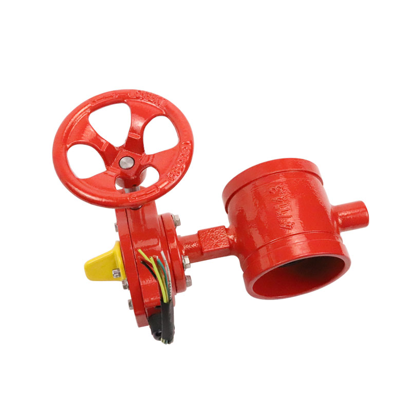
Grooved butterfly valves earn their place in fire sprinkler layouts when they're positioned to isolate trouble without shutting down entire buildings. The riser is the natural starting point—mounting a grooved butterfly valve just downstream of the main alarm check or wet pipe valve gives you a single point of control for the whole system. But that alone doesn't deliver maximum coverage; it just creates a master switch. The real value appears when you carry the same valve type into each floor control assembly and zone line, letting maintenance or emergency crews drain one floor or wing while the rest stay charged and ready.
Zone placement calls for more than just cutting into the pipe. A grooved butterfly valve works best when it's paired with a supervised tamper switch and positioned on the supply side of each zone's flow switch, at a height that doesn't turn a simple isolation into a ladder job. Avoid burying them above hard ceilings or behind fixed equipment—those locations defeat the purpose of quick manual operation. Instead, look for riser rooms, corridor access panels, or dedicated valve closets where the gear operator can swing freely without colliding with adjacent pipe, conduit, or ductwork.
Coverage isn't about adding more valves; it's about placing them so every branch line falls inside a predictable isolation boundary. On multi-story jobs, that usually means one grooved butterfly valve per floor at the riser takeoff, plus additional valves on large horizontal zone mains serving areas like parking decks, attics, or separate occupancy pods. Keep the spacing logical: if a valve closure leaves an entire 40,000-square-foot floor without protection, you've gained little over a full-building shutdown. The goal is to match each valve's reach to the area your team is willing to drain, refill, and test in a single outage window. That's how grooved butterfly valves go from simple components to the backbone of a maintainable sprinkler system.
UL/FM Marks Explained: What Actually Happens During Testing
When a product carries a UL or FM mark, it's not because someone glanced at a schematic and signed off. These certifications come from destructive, hands-on testing where engineers deliberately push devices past their rated limits. A circuit breaker, for instance, may be forced to interrupt thousands of amps of fault current over and over, while technicians watch for glowing contacts, cracked housings, or any arc flash that could ignite nearby materials. The goal is not to see if the product works under ideal conditions, but to find exactly how and when it fails—and whether that failure stays contained.
Environmental stress is just as brutal as the electrical abuse. Samples are often baked in humidity chambers for weeks, then suddenly hit with full rated voltage to check for insulation breakdown. Some products get vibrated on shaker tables, dropped onto concrete, or sprayed with salt mist to simulate years of corrosion in a coastal factory. UL and FM don't follow identical playbooks—UL tends to focus on shock and fire hazards for general use, while FM leans into property loss prevention, like verifying that a sprinkler head actually opens at the right temperature under sustained water pressure. But both share a refusal to accept manufacturer claims at face value.
Passing the lab gauntlet is only half the story. After certification, both UL and FM send inspectors to factories unannounced, pulling random units off the production line to compare against the original tested samples. A mark on the label means the design survived the worst-case scenarios, and that the factory keeps making the same product month after month. That's the real value of those tiny logos—they're a promise backed by broken parts, scorched terminals, and a lot of very deliberate destruction.
Inside a Fire-Rated Butterfly Valve: Disc, Seat, and Stem Choices
The disc in a fire-rated butterfly valve does more than just block flow. You'll often see it cast from ductile iron and then plated with nickel or coated with epoxy for basic corrosion resistance, but where temperatures climb, a solid stainless steel disc becomes the safer bet. Its edge profile matters too—some discs have a polished, rounded rim that slides against the seat with less friction, while others feature a sharper edge to cut through any debris that might have settled on the sealing surface. The disc's thickness is also tuned to resist warping under uneven thermal loads, which is what you'd expect when one side of the valve faces a fire and the other side still carries water or gas.
Seat selection is where fire-rated designs really separate from standard butterfly valves. A typical EPDM or nitrile seat will soften and burn away once temperatures exceed a few hundred degrees, so manufacturers often add a secondary metal seat behind the elastomer. That metal ring, usually stainless steel, takes over when the polymer is gone, allowing the valve to maintain a reduced but still measurable seal. Some designs use a graphite-impregnated seat or a flexible graphite ring that expands slightly when heated, filling the gap between disc and body. PTFE seats show up in chemical service, but they need a resilient backer because PTFE cold-flows under pressure. The real trick is ensuring the primary seat doesn't melt into a sticky mess that prevents the metal backup from engaging.
Stem choices tend to be less visible but no less critical. A blowout-proof stem is non-negotiable for fire service—look for a shoulder or retaining ring that prevents the stem from being pushed out under pressure if the handle or actuator is removed. Most stems are turned from stainless steel bar, often 17-4 PH or 316, because they need to resist both galling and corrosion while transmitting torque through a packing that still holds when the surrounding body starts to glow. Some manufacturers split the stem into upper and lower sections, joined by a shear pin that fails predictably if the disc jams, protecting the actuator from damage. Anti-static grounding between the stem and body is another quiet feature, preventing spark discharge in flammable atmospheres even if the valve is used as an emergency shutoff.
Why Contractors Prefer Grooved Connections on Tight Deadlines
On a tight deadline, the longest part of traditional pipe joining isn't the welding itself—it's the waiting around it. Grooved connections cut out beveling, hot work permits, and cool-down time before pressure testing. A couple of bolts torqued with a standard ratchet and the joint is ready, which lets a small crew rough in large sections of mechanical room piping in a single shift.
Rework is what really kills a schedule, and grooved joints give you immediate visual confirmation that the pipe is seated correctly. There's no guesswork about root gaps or weld quality. If the coupling doesn't drop into the groove, you fix it right then, not after an inspector flags it days later. That predictability lets foremen move labor to other areas instead of holding welders on one line.
Grooved connections also make scheduling more flexible. Since installation doesn't depend on weather or confined-space welding restrictions, the same crew can close out more runs in less time. When the general contractor compresses the sequence, mechanical teams reach for grooved joints because the speed is consistent—no extra trades standing by, no waiting on permits, just pipe in place and the next task started.
Pressure Drop and Flow Rate: Matching Valve Size to System Demand
Oversizing a valve often feels safe, but it quietly drives up energy costs and control instability. A valve that’s too large spends most of its life barely cracked open, forcing the system to work against an artificially steep pressure drop. The result is not just wasted pump horsepower—it’s chattering, erosion near the seat, and a hunting loop that never quite settles. Correct sizing starts with the actual required flow coefficient, not the line size.
Pressure drop across the valve isn’t a fixed penalty; it should be selected to give the valve authority over its portion of the circuit. Aim for a drop that’s meaningful but not excessive—typically 15 to 30 percent of the total dynamic loss in that branch. When the valve is matched to real demand, the characteristic curve shifts from an on/off switch to a smooth, predictable relationship between stem position and flow. This gives the control loop room to breathe without forcing the actuator to fight against a near-closed seat.
Flow rate matters more than pipe diameter here. A good practice is to calculate the maximum and minimum flow the valve will actually see, then pick a size where those conditions fall within 20 to 80 percent of the valve’s travel. Ignore the temptation to match connection size by default—reducing trim or using a smaller body with reducers is often cheaper over the life of the system than buying a full-line-size valve that never modulates well.
Low-Frequency Use, High-Stakes Maintenance: A Practical Schedule
When a machine sits idle for weeks, its maintenance needs shift from routine wear-and-tear to a different set of risks: seals drying out, lubricants settling, batteries draining, and moisture creeping into sensitive components. The temptation is to ignore it until the next job, but that is exactly when failures strike. A practical schedule starts with a simple calendar reminder every 30 days, even if nothing seems wrong. On that day, run the equipment for ten to fifteen minutes under light load, just enough to circulate fluids and keep moving parts from stiffening. For engines, this means turning over the starter and letting it reach normal operating temperature; for hydraulic systems, cycle every cylinder once or twice. Write the date and any odd sound or leak in a log kept near the machine, not in a cloud app you will forget to open.
Beyond the monthly wake-up call, build a short checklist for the specific risks of low use. Check tire pressures and look for flat spots if the unit has been stationary for long stretches. Inspect belts for cracks that develop from sitting in one position, and replace fuel that has been in the tank for more than ninety days unless you treated it with a stabilizer. Grease fittings may look fine, but old grease hardens and loses its ability to protect pins and bushings; a quick pump on each zerk takes two minutes and prevents a seized joint later. If the equipment lives outdoors, pay extra attention to electrical connections and battery terminals, which corrode faster when not regularly warmed by use. A trickle charger or battery disconnect switch is a cheap safeguard against a dead start on the day you really need it.
The schedule itself should live on paper or a simple wall chart, not buried in a digital task manager that sends alerts you dismiss without thinking. Tape it to the machine, or hang it on the shop door. The goal is not to turn low-use equipment into a full-time maintenance burden, but to make the crucial checks so routine that they take less than an hour a month. When you skip a month, do not shrug it off; schedule a slightly longer session next time to cover what was missed. The cost of that hour is trivial compared to a failed pump or snapped belt on the one morning the weather finally breaks and the job cannot wait. Treat these checks like checking the oil in a car you rarely drive: you may not need to do it often, but you absolutely cannot afford to skip it.
FAQ
The grooved ends allow rapid installation and easier maintenance, which is essential in fire protection networks. A reliable valve should also have a supervised open position, a ductile iron body, and an EPDM or nitrile seat that can handle water, foam, or air without degrading.
UL typically evaluates the valve as a component for listing in fire protection systems, while FM focuses on property loss prevention and may require additional testing for durability and low friction loss. Both approvals indicate the valve has met rigorous performance standards, but some jurisdictions or insurers might specifically require one over the other.
Grooved connections eliminate the need for flange alignment and bolt hole matching, which speeds up installation and reduces labor costs. They also allow slight angular deflection and absorb some vibration, making the system less prone to leaks during seismic events or water hammer.
In fire protection, these valves typically range from 2 inches up to 12 inches, with pressure ratings of 300 psi for smaller sizes and 175 psi to 200 psi for larger ones. Always verify the exact rating against the system's working pressure, as some listings cover only specific size-pressure combinations.
Install the valve with the stem horizontal or vertical depending on the manufacturer's instructions, and make sure the indicator clearly shows the open or closed state. Avoid using the valve as a support point for piping, and tighten grooved couplings evenly to prevent distortion of the disc or seat.
Exercise the valve from fully open to fully closed at least once a year to prevent sediment buildup and verify the gear operator moves smoothly. Check the grooved couplings for signs of corrosion or gasket extrusion, and confirm the tamper switch or supervisory signal still transmits correctly.
Yes, but you need to confirm the seat material is compatible with the system type. For dry systems, the valve may see compressed air or nitrogen, so a seat with good low-temperature flexibility and resistance to drying out is important. Many UL FM listed grooved butterfly valves are approved for both applications when properly selected.
Conclusion
Fire protection systems live or die by how well each valve holds its position from the riser down to the last zone. Grooved butterfly valves carrying both UL and FM marks have earned that listing through brutal testing: repeated open-close cycles under pressure, seat leakage checks, and full-scale burn tests that push the assembly past its rated temperature. Internally, the disc, seat, and stem materials matter more than spec sheets often admit. A ductile iron body with an EPDM or nitrile seat, a stainless or nickel-plated disc, and a blowout-proof stem can mean the difference between a valve that throttles accurately during a fire and one that jams or leaks when the alarm panel finally calls for water.
Contractors keep returning to grooved connections because they cut installation time dramatically—no hot work permits, no weld inspections, just a gasket, housing, and torque wrench. But field success also depends on sizing the valve against the system's pressure drop and flow demand; an oversized valve wastes money and an undersized one starves distant sprinklers. Since these valves sit idle most of their lives, maintenance often gets skipped, but a practical schedule of annual visual checks, lubrication of the gear operator, and occasional partial stroke testing catches corrosion and seat set before they become failures. That low-frequency, high-stakes reality is exactly why the right UL/FM grooved butterfly valve earns its place in a fire protection design.
Contact Us
Contact Person: George
Email: [email protected]
Tel/WhatsApp: 13863633883
Website: https://www.es-fire.com